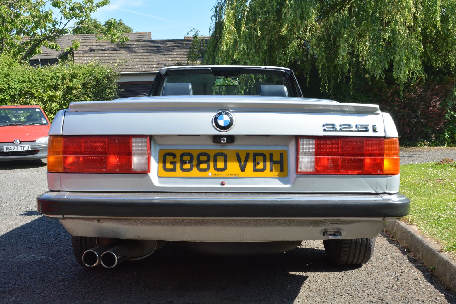
I have a 1990 E30 325i Convertible. The brakes have always been less than perfect, so after fitting a new master cylinder along with new callipers, discs, flexible hoses and a few hard lines as well, I was still not convinced that even after presure bleeding several times, that I had all the air out of the system.
I'd read that later BMW's could be taken to a dealer and have the ABS solenoids put into some kind of service mode to help push trapped air out of the ABS pump block, but that the E30 did not have this facility, some say that you need to have the pump unit blead by a specialist, anyway, I searched through a number of Bosch ABS purge documents and decided to have a go myself. Bosch always state that a pressure bleeder is essential to correctly purge the ABS, so this is a requirement.
I lashed up a simple system to activate the ABS as if it were operating under a heavy breaking scenario with the pump and solenoids active, then bleed each solenoid pump line whilst this was happening.
WARNING!
Don't do any work on the ABS without first removing the multi pin connector for the ABS ECU - it's sensitive and can be fried with great ease. However the ABS block itself contains only solenoids and no sensitive electronics -
Here's the schematic - we need to send 12v from the battery to each pin 30 of both relays - this will a) run the pump and B) operate each solenoid in turn, as we earth them with our earth cable.

For ease of working I used a Sealy Presuure Bleeder and two cables that I made up out of a few workshop bits, namely a couple of metres of lash up wire, fairly chunky, an in-line fuse holder with a 10 amp fuse, two crocodile clips to make connection quick, easy and safe, and a variety pack of heat shrink tubing. I made up two cables one is 1.5 meters long, with a crock clip at one end for the battery positive, a 10 amp fuse in line and at the other end a pair of "plugs" made by baring 2 cms of the cable, folding it over and heat shrinking the result, leaving a section of bare wire, forming a "plug" which push into the relay sockets.
These two plugs push into the holes numbered 30 left free after removing both the protection relay and the pump relay from the ABS unit.
 |
| power lead with two "plugs" it has an in-line 10amp fuse and a crock clip at the other end for battery positive. |
The second cable is half a meter long, a croc clip at one end to attach to the car chassis earth in the engine compartment and the other is a socket to attach to either pin one, three or five of the ABS control multi way connector. This activates the desired solenoid within the pump.
I'm going to assume that the car is ready to bleed all round, put the whole car up on stands and get the wheels off, This will allow you tp bleed each corner simply, no fuss. Set up a fluid collection jar and bleed nipple spanner on the rear right hand calliper, ie furthest from the master - check that the pressure bleeder is loaded, pressure tested and ready to go. Do not exceed 20psi on the pressure bleeder, and not less than 10psi, just keep an eye on fluid levels and pressure.
 |
| Earth cable "socket" and crock clip |
I'm going to assume that the car is ready to bleed all round, put the whole car up on stands and get the wheels off, This will allow you tp bleed each corner simply, no fuss. Set up a fluid collection jar and bleed nipple spanner on the rear right hand calliper, ie furthest from the master - check that the pressure bleeder is loaded, pressure tested and ready to go. Do not exceed 20psi on the pressure bleeder, and not less than 10psi, just keep an eye on fluid levels and pressure.
First, isolate the ABS by removing the cover - you need a torx set for this, then also remove the cable clamp and withdraw it - then weedle the plug out, it can be a bit of a pain, but it will come. Now carefully remove the two relays and set them aside - you cant mix them up as the pin layouts are different.
 |
| This shows the power lead plugged in to the pin 30's and the earth lead connected to pin 5 (rear solenoid) |
Select cable 2, connecting the socket end to pin 5 and clamping the croc to a suitable stud - this hard wires the trigger for the rear solenoid - on the E30 there are 3 solenoids, one each for the fronts and a shared one for both rear brakes,
Now connect the two plugs of cable one to both pin 30's one on each relay socket - pass around the car and briefly touch the croc to battery positive - you should hear the pump start up in the ABS unit. So we are ready to bleed.
Crack open the nipple on rear right and confirm fluid flow which shows the pressure bleeder is pushing fluid through the system, now push the brake pedal hard and touch cable one croc clip to the battery positive,- this will produce a rapdid clicking sound firing up the solenoid as well as the sound of the pump running - the solenoid clicks will fade and stop after a few seconds- disconnect the power, release the pedal then press hard again, re-apply the power until solenoid stops clicking. Repeat 5 times - this should have purged the rear solenoid of air, however:
 |
| shows a close up of the power cable feeding pins 30 on both relay sockets. |
Crack open the nipple on rear right and confirm fluid flow which shows the pressure bleeder is pushing fluid through the system, now push the brake pedal hard and touch cable one croc clip to the battery positive,- this will produce a rapdid clicking sound firing up the solenoid as well as the sound of the pump running - the solenoid clicks will fade and stop after a few seconds- disconnect the power, release the pedal then press hard again, re-apply the power until solenoid stops clicking. Repeat 5 times - this should have purged the rear solenoid of air, however:
Leave rear brake line bleeding until you feel enough fluid has passed to eject any air.
Now close off rear right nipple and switch to rear left - pressure bleed this side until satisfied -
(You do not need to re activate the rear solenoid - as it serves both sides and has been purged already)
Now close off rear right nipple and switch to rear left - pressure bleed this side until satisfied -
(You do not need to re activate the rear solenoid - as it serves both sides and has been purged already)
Now go about bleeding and purging the front solenoids - attach the earthing cable to pin 3 on the ABS unit - selecting the front right solenoid path - crack open the bleed nipple on the front right callipe and check your fluid flow, and repeat the brake peddle pushes connecting power each time at the battery thus activating the solenoid whilst running the pump. Again, bleed out until your happy.
Switch the earthing cable to pin one and bleed the front left in the same manner - when finished, release the pressure bleeder, check your fluid levels and enjoy a rock solid pedal.
One or two things to check:
If you are not using a pressure bleeder, but are following the normal 2 person approach,
there's an extra detail given in the E30 Bentley Sevice Manual:
Have a helper slowly pump the brake pedal about three
times (1 2 times or more on cars with ABS) . The last time, hold
the pedal down. Slowly open the bleeder valve approximately
one-half turn. Close the bleeder valve when brake fluid stops
flowing from it, then release the brake pedal.
Thats 12 times or more!!
If you find that one or more bleed nipples produces a very low fluid flow when opened up, of course check the nipple, but the most likely culprit is the ABS block itself. Inside the unit are 6 filters which over the years become seriously blocked, preventing fluid passage. Here's what they look like.
Here's some cleaned filters before the rebuild:
If your ABS is in this condition, the only course of action is to open it, clean everything
and rebuild using new O rings. Alternatively replace the block with a second hand one with good flow from each output port - final route is delete the ABS altogether.
ABS System Faults
The signs of a malfunctioning ABS modulator can mimic problems with calipers, brake hoses or the master cylinder. Common complaints often include pulling brakes, long stops and low brake pedal. The main cause of these issues is the valve seats and pintles can become stuck or not seat properly due to debris, corrosion or contaminated brake fluid.
Corrosion results in the depletion of the buffers and anti-corrosion additives in the brake fluid, as the ABS modulator has a variety of metals in close contact. As the brake fluid corrodes the lines that are brazed with copper and the ferrous components, ions of the metals are release into the fluid. Since the ABS modulator has different metals, they act as anodes and cathodes. Some attract ions of copper while others are eaten away.
For a valve in the ABS modulator, the ions can plate the pintles and seats. This can prevent operation by causing it to stick and even stay open.
Theory of Operation
To diagnoses ABS modulator valve problems, you have to know how they work to apply, hold or release the brakes. Each brake corner has two valves. The inlet/isolation valve isolates the brake corner from the ABS pump/accumulator and the master cylinder. The outlet/dump valve allows brake pressure to be released. These valves work together to perform the following braking tasks:
Apply
When the master cylinder applies pressure, it goes directly to the wheel because the outlet/dump solenoid is closed. This is a normal braking event. The unit is in a “passive” state. It is also the position the ABS system will go to if the system is disabled.
Hold
If the system senses a wheel is locked, the inlet/isolation solenoid is closed to prevent any more pressure from the master from reaching the wheel. The wheel might start to turn. This can create a brake-pull condition.
Release
if the wheel does not start to turn, the outlet/dump valve will open. This will release or bleed off the hydraulic pressure that is holding the wheel. The wheel will now rotate.
Reapply
Since pressure from the master cylinder has been bled off, the pump in the ABS modulator will spool up and apply pressure. The outlet valve is closed and the inlet valve is opened. The pump applies pressure to the wheel. If the wheel is still outside the wheel slip parameters, the cycle will start over. This happens very quickly. The operation of the solenoids and pump will cause a “kick back” or pulsation in the pedal.
Diagnostic Modes
If the inlet/isolation valve is stuck open, it will not affect normal braking in any way; it will only hurt the ABS system. This could lead to a pulling condition during ABS activation. If an outlet/dump valve is stuck open in one circuit, this could cause a pull condition during normal braking. This is due to the loss of brake pressure at a wheel. If more than one valve leaks or is not able to seat, it could cause a longer than normal stop if the ABS is activated.
One or two things to check:
If you are not using a pressure bleeder, but are following the normal 2 person approach,
there's an extra detail given in the E30 Bentley Sevice Manual:
Have a helper slowly pump the brake pedal about three
times (1 2 times or more on cars with ABS) . The last time, hold
the pedal down. Slowly open the bleeder valve approximately
one-half turn. Close the bleeder valve when brake fluid stops
flowing from it, then release the brake pedal.
Thats 12 times or more!!
If you find that one or more bleed nipples produces a very low fluid flow when opened up, of course check the nipple, but the most likely culprit is the ABS block itself. Inside the unit are 6 filters which over the years become seriously blocked, preventing fluid passage. Here's what they look like.
 |
| This is an opened ABS block that would pass almost no fluid to the right hand front calliper - brakes were poor and insensitive. |
 |
| cleaned "Input" filters |
If your ABS is in this condition, the only course of action is to open it, clean everything
and rebuild using new O rings. Alternatively replace the block with a second hand one with good flow from each output port - final route is delete the ABS altogether.
 |
| O rings and solenoid unit with cleaned filter. |
ABS System Faults
The signs of a malfunctioning ABS modulator can mimic problems with calipers, brake hoses or the master cylinder. Common complaints often include pulling brakes, long stops and low brake pedal. The main cause of these issues is the valve seats and pintles can become stuck or not seat properly due to debris, corrosion or contaminated brake fluid.
Corrosion results in the depletion of the buffers and anti-corrosion additives in the brake fluid, as the ABS modulator has a variety of metals in close contact. As the brake fluid corrodes the lines that are brazed with copper and the ferrous components, ions of the metals are release into the fluid. Since the ABS modulator has different metals, they act as anodes and cathodes. Some attract ions of copper while others are eaten away.
For a valve in the ABS modulator, the ions can plate the pintles and seats. This can prevent operation by causing it to stick and even stay open.
Theory of Operation
To diagnoses ABS modulator valve problems, you have to know how they work to apply, hold or release the brakes. Each brake corner has two valves. The inlet/isolation valve isolates the brake corner from the ABS pump/accumulator and the master cylinder. The outlet/dump valve allows brake pressure to be released. These valves work together to perform the following braking tasks:
Apply
When the master cylinder applies pressure, it goes directly to the wheel because the outlet/dump solenoid is closed. This is a normal braking event. The unit is in a “passive” state. It is also the position the ABS system will go to if the system is disabled.
Hold
If the system senses a wheel is locked, the inlet/isolation solenoid is closed to prevent any more pressure from the master from reaching the wheel. The wheel might start to turn. This can create a brake-pull condition.
Release
if the wheel does not start to turn, the outlet/dump valve will open. This will release or bleed off the hydraulic pressure that is holding the wheel. The wheel will now rotate.
Reapply
Since pressure from the master cylinder has been bled off, the pump in the ABS modulator will spool up and apply pressure. The outlet valve is closed and the inlet valve is opened. The pump applies pressure to the wheel. If the wheel is still outside the wheel slip parameters, the cycle will start over. This happens very quickly. The operation of the solenoids and pump will cause a “kick back” or pulsation in the pedal.
Diagnostic Modes
If the inlet/isolation valve is stuck open, it will not affect normal braking in any way; it will only hurt the ABS system. This could lead to a pulling condition during ABS activation. If an outlet/dump valve is stuck open in one circuit, this could cause a pull condition during normal braking. This is due to the loss of brake pressure at a wheel. If more than one valve leaks or is not able to seat, it could cause a longer than normal stop if the ABS is activated.